But as soon as I pull up the SOP2 and trying to connect through the cc3200tool, I wont see anything else than a timeout. The box is booting as expected (green light, no sound):
(venv) root@testing:/usr/src/venv# cc3200tool -p /dev/ttyUSB0 --reset dtr read_all_files ExtractedFromBox/
2025-03-14 13:26:51,886 – Connecting to target…
2025-03-14 13:26:54,243 – timed out while waiting for ack
2025-03-14 13:26:56,499 – timed out while waiting for ack
2025-03-14 13:26:58,759 – timed out while waiting for ack
2025-03-14 13:27:01,019 – timed out while waiting for ack
2025-03-14 13:27:03,275 – timed out while waiting for ack
2025-03-14 13:27:03,275 – Could not connect to target: Did not get ACK on break condition
(venv) root@testing:/usr/src/venv#
If I do not connect SOP2 to anything, I see at least the cc3200tool is able to detect the debug output, but of course it cannot continue.
(venv) root@testing:/usr/src/venv# cc3200tool -p /dev/ttyUSB0 --reset dtr read_all_files ExtractedFromBox/
2025-03-14 13:46:30,255 – Connecting to target…
2025-03-14 13:46:35,348 – Connected, reading version…
2025-03-14 13:46:53,188 – timed out while waiting for ack
2025-03-14 13:46:53,189 – Could not connect to target: No ack for packet opcode=0x2f
(venv) root@testing:/usr/src/venv#
What am I doing wrong? What can I do? Does anybody has a clue for me?
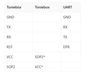
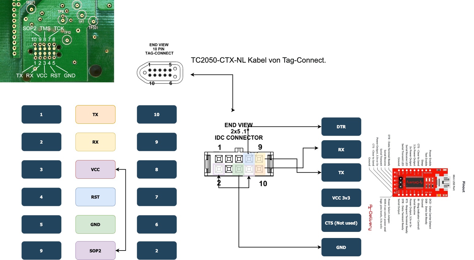
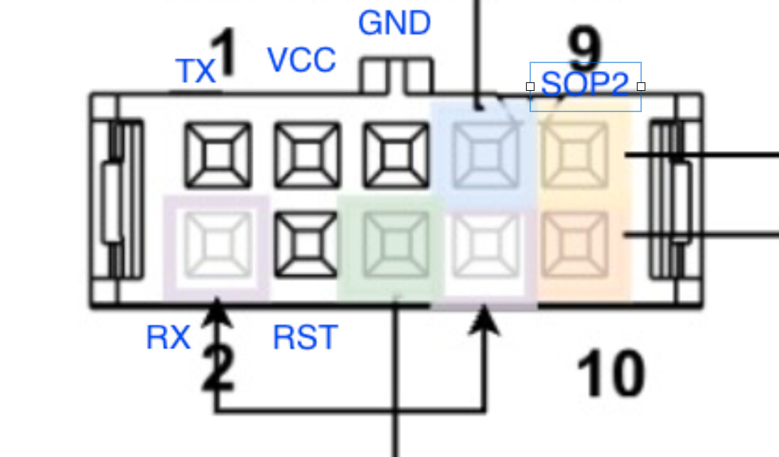
Which kind of wrong wiring could be leading to such a behaviour? As I wrote, TX/RX works with the Debug from orig. Bootloader. Beside this I also wrote, SOP2 is connected to VCC, what else beside this is necessary? At least nothing more mentioned in the guide.
Thanks
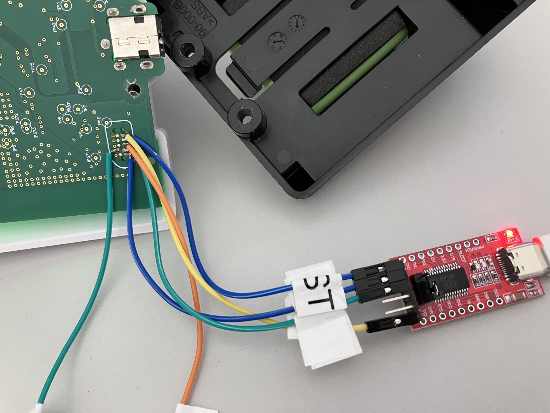
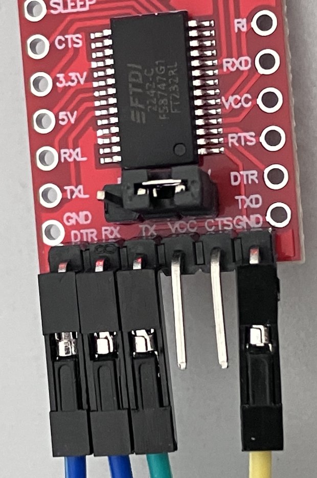
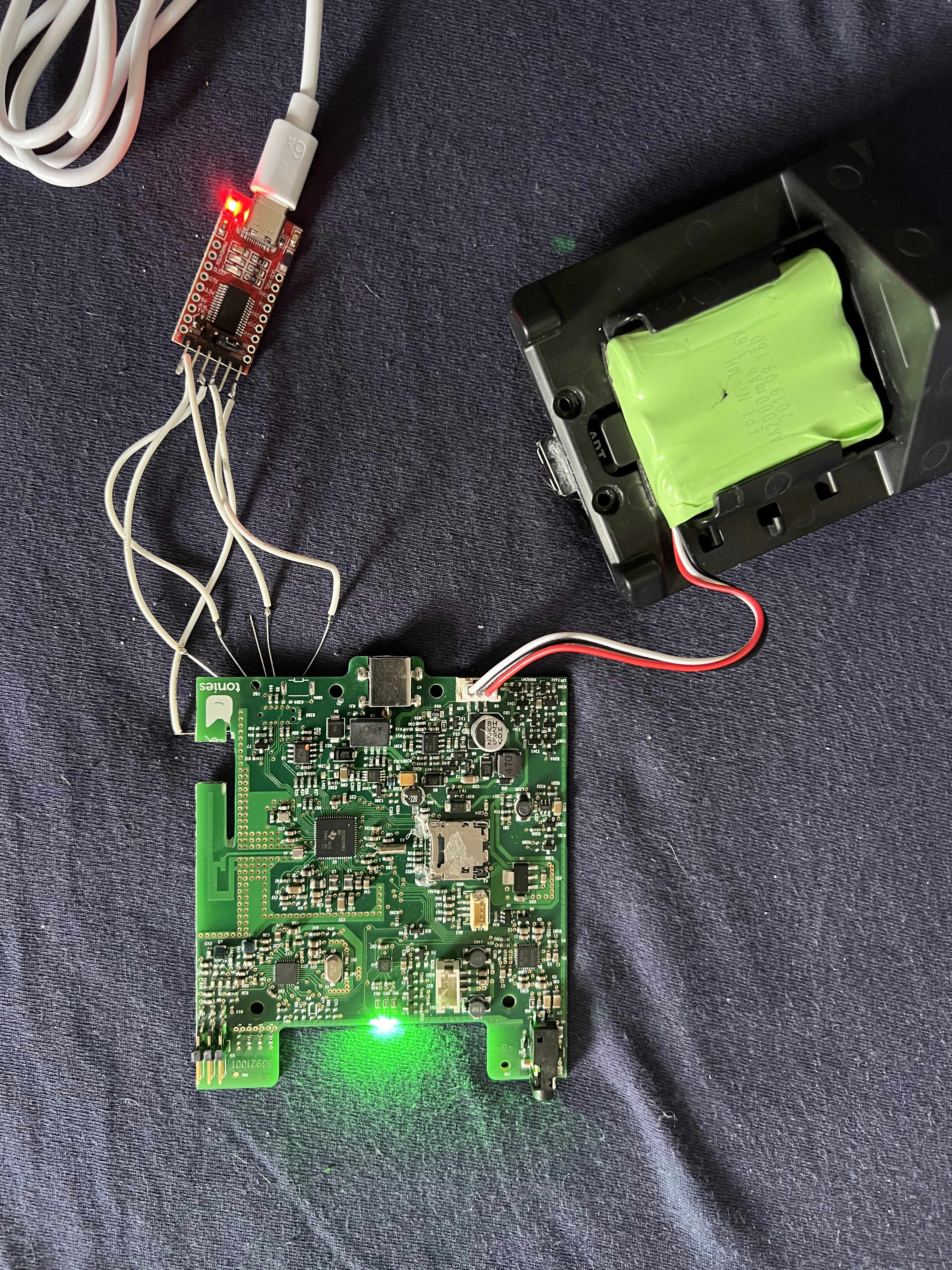
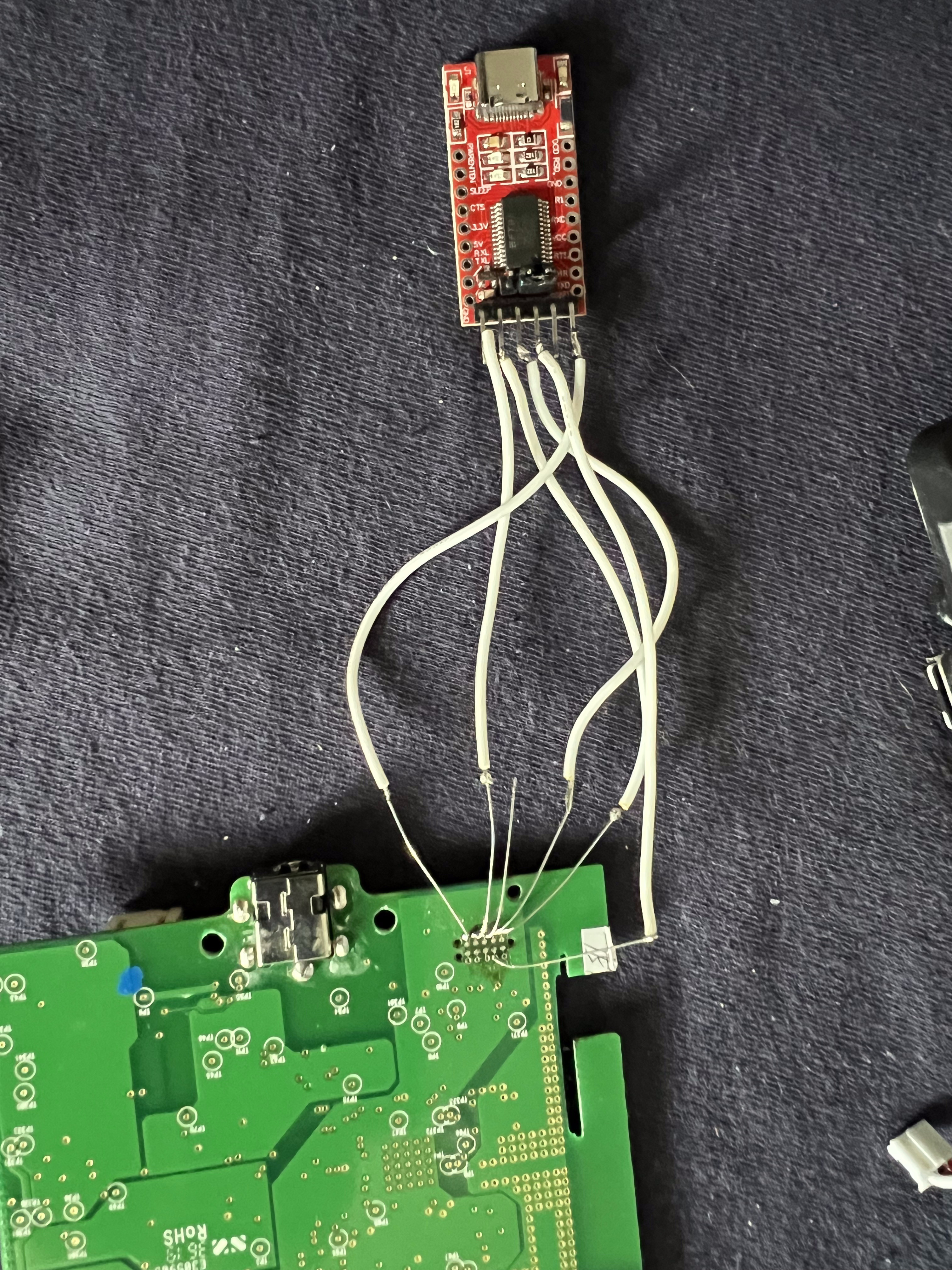
Here are some pictures showing my setup, I think its better than just explanation.
SOP2 and VCC not connected together at this moment. Fyi, I tried both, SOP2 ↔ VCC of the Toniebox and SOP2 connected to the VCC of the UART interface. When SOP2 connected to the VCC of the UART, the box simply boots as normal.
Hi terner,
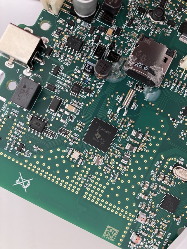
I have the exact same issue as you. I can see the debug output at regular boot just fine as you. We also seem to have the same board version.
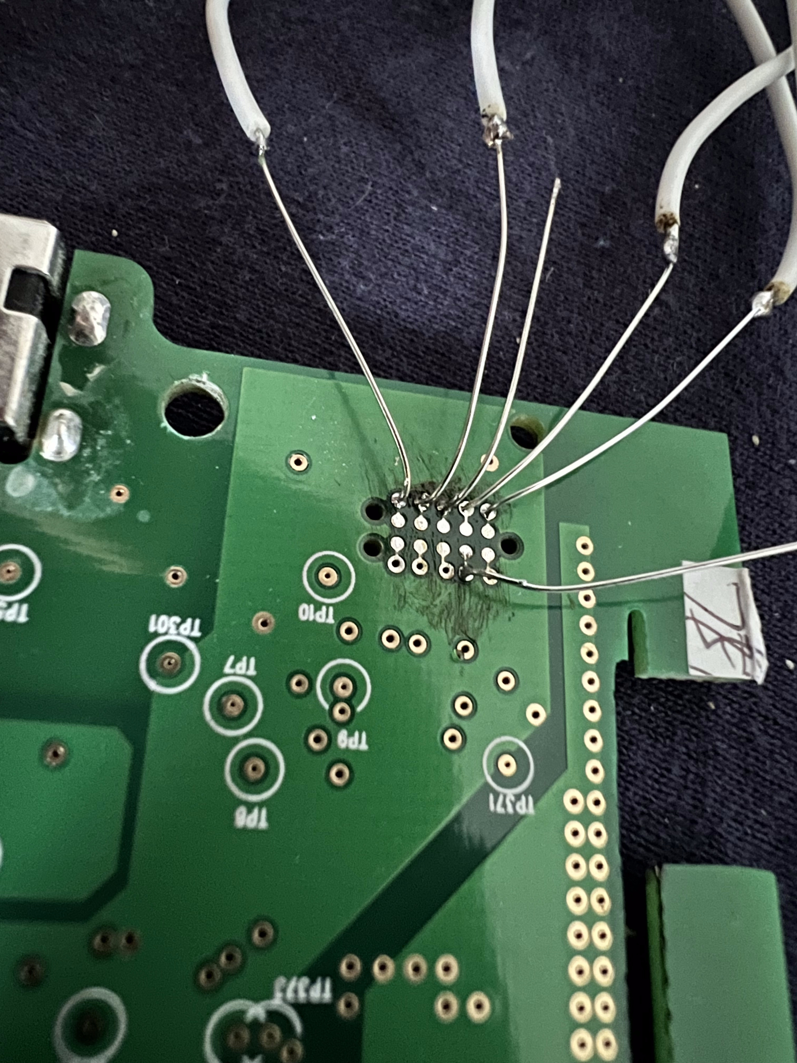
I also soldered contacts to the debug port, but instead of using a FTDI UART I only have a CH3400 on an Arduino Nano board at the moment, where I keep RST pulled to GND to bypass the Arduino. So I have to do the reset manually, but it seems to work fine.
I can also get the output “Connected, reading version…” and then get the timeout because of the missing ack packet opcode=0x2f.
My next try would be to use a better USB to UART converter and check the soldering, but in my opinion it should work, as the cc3200tool says it has connected and the debug output can be read.
Could it be possible, that something on the board has changed, so the reading the memory is prohibited? Our PCBs e.g. look different from the guide, the debug port has some contour in the shape of the connector drawn around. Has anybody else managed to read the memory of this version?
I have the same problem. When I don’t connect SOP2, I get a connection but no access. When I connect SOP2 to VCC from the adapter or the box, the box doesn’t boot. The LED just stays green — which is probably correct. But the RST doesn’t seem to work in this state. The LED on the adapter lights up and RST is pulled LOW, but nothing happens. I also tried it manually. The CC3200 doesn’t seem to respond to RST when SOP2 is high. As I said, without SOP2 connected, RST works. I’ve rewired everything twice and checked all connections. The 3.3V are correct.
I finally got it done with a new UART board, the same as @terner has.
A few things i noticed along the way, which might help somebody:
Try to change Rx and Tx, i always mix them up
If the wiring is correct, you should at least be able to see the debug output at normal startup. If this is not working, you most likely won’t be able to read/write via cc3200tool
Even if everything is correct, it sometimes doesn#t work because of bad connection between jumper cable and soldered wire. Retry a few times and also do power reset on the UART adapter and the box
@bjoe10 can you see the debug output at regular startup? Have you checked this first?
Yes, on normal Startup there is a connection. I flashed a esp32 box successfully with the adapter so the adapter is fine i think. I tried all i can imagine but no luck with the cc board.
Thanks for your reply. i tried your pinout. Still not working. Led Stays in all cases solid green. But no connection possible.
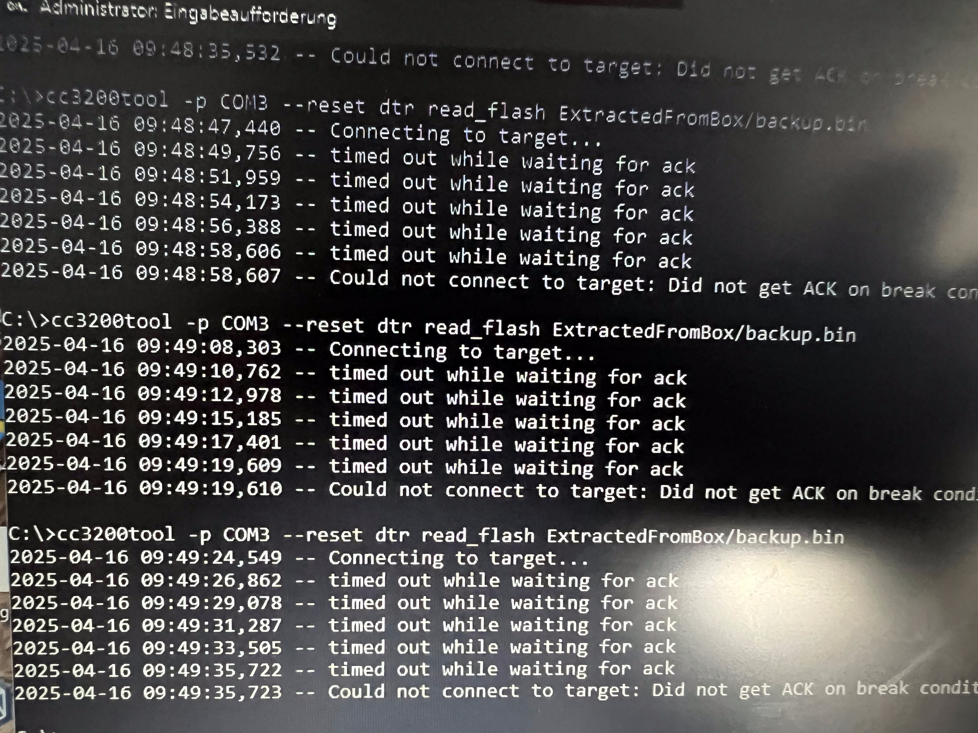
user@MacBookPro cc3200tool % cc3200tool -p /dev/tty.usbserial-A50285BI read_all_files ExtractedFromBox/ read_flash backup.bin
2025-05-23 12:00:53,666 – Connecting to target…
2025-05-23 12:00:56,084 – timed out while waiting for ack
2025-05-23 12:00:58,501 – timed out while waiting for ack
2025-05-23 12:01:00,923 – timed out while waiting for ack
2025-05-23 12:01:03,343 – timed out while waiting for ack
2025-05-23 12:01:05,759 – timed out while waiting for ack
2025-05-23 12:01:05,764 – Could not connect to target: Did not get ACK on break condition
Did you have other help please.
Thanks in advanced.
Add --reset dtr in your command. Then it should work.
I quote the guide in teddycloud:
If your UART programmer has a DTR pin, use --reset dtr before each command (e.g., cc3200tool -p COM3 --reset dtr ...). Otherwise, you’ll need to briefly connect the RST Pin (Toniebox) to GND before each command. If you skip this step, the console will display “timed out while waiting for ack” and abort the operation.