Hey Everyone,
as I had trouble flashing my cc3235 I want to describe them and also how I got it running.
I have IS25LQ032B flash chip.
The CH341A Programmer has the problem, that the data lines still drive with 5V instead of 3.3V. As I had concerns destroying my chip, I applied a fix to 3.3V 3.3V Fix.
I tested the Programmer without connecting to the flash, and it was correctly recognized by Linux and the both leds behaved okayish and where quite brightly glowing.
Then I attached the SOP8 clamp and put the small pcb into the programmer like described in this post. The battery was disconnected and I put the programmer into the USB port.
The Run LED of the programmer became dimmed down with the flash connected and the programmer was not recognized. Flashrom didn’t detect a programmer anymore.
Then I put in the programmer first and afterwards connected the small PCB to the programmer. The programmer was detected fine but as soon as the PCB was connected it got disconnected from linux. sudo dmesg showed the disconnects quite prominent. I measured the power between VCC of usb programmer and flash cip and it took already 380mA and I assume with the power for the programmer it draw too much for my usb port (Lenovo T480) and disconnected. So I had no luck using this programmer. I had concerns to connect the battery in parallel so i didn’t try that.
I had another CH341A multipurpose USB stick laying around Module CH341A USB UART/I2C/SPI and that one was not drawing too much power with the flash connected. But still, the readout was not possible as the received values where always a bit different. It already got the manufacturer id and device id correct (0x9d & 0x4016) most of the time but SFDP was not detected correctly. (The IS25LQ032B is not supported directly by flashrom but flashrom and this chip supports SFDP, so it is supported that way)
So perhaps it still draws too much power to have something in a state which is not ready to read. So the connection wasn’t stable to get it working reliable.
flashrom -V -p ch341a_spi
Probing for Generic unknown SPI chip (RDID), 0 kB: compare_id: id1 0x9d, id2 0x4016
Added layout entry 00000000 - ffffffff named complete flash
Found Generic flash chip "unknown SPI chip (RDID)" (0 kB, SPI) on ch341a_spi.
Probing for Generic unknown SPI chip (REMS), 0 kB: compare_id: id1 0x9d, id2 0x15
Found Generic flash chip "unknown SPI chip (RDID)" (0 kB, SPI).
===
This flash part has status NOT WORKING for operations: PROBE READ ERASE WRITE
This flash part has status UNTESTED for operations: WP
Until here, I had connected:
Flash / USB Module
Pin1 CE# → CS0
Pin 2 SO → MISO
Pin 3 WP# → VCC 3.3V
Pin 4 GND → GND
Pin 5 SI → MOSI
Pin 6 SCK - > SCK
Pin 7 HOLD# → Not connected
Pin 8 VCC → VCC 3.3V
What I then did changed all to a good:
I disconnected Pin 1 VCC and Pin 3 WP# and put it into the USB port.
The toniebox led does not light now (if it already glows very very lightly, you can skip the next step).
Connect Pin 1 VCC to 3.3V for about 2s (wait for the solid, very bright glow)
Disconnect Pin 1 VCC again
The toniebox led should still glow green but very very dimmed. Look closely.
Probing for Unknown SFDP-capable chip, 0 kB: Parsing JEDEC flash parameter table... done.
Support for SFDP Page with ID 0x9d not implemented, skipping it.
===
SFDP has autodetected a flash chip.
All standard operations (read, verify, erase and write) should work.
Additionally, flashrom supports RPMC commands via SFDP autodetection.
We may add support for more features via SFDP in future.
If you are interested, join us on the mailing list https://flashrom.org/contact.html#mailing-list-1
===
Added layout entry 00000000 - 003fffff named complete flash
Found Unknown flash chip "SFDP-capable chip" (4096 kB, SPI) on ch341a_spi.
Now the data can be read reliable with flashrom!
Last thing is writing, without WP# (Writeprotect) connected to VCC, the write command can not succeed. So just before calling the write command, just connect Pin 3 WP# to VCC and it worked.
My resulting connections:
Flash / USB Module
Pin1 CE# → CS0
Pin 2 SO → MISO
Pin 3 WP# → only connected right before calling the write command
Pin 4 GND → GND
Pin 5 SI → MOSI
Pin 6 SCK - > SCK
Pin 7 HOLD# → Not connected
Pin 8 VCC → NOT CONNECTED (only for 1-2s to get the low glow led state)
The power which comes through the data lines seems to be enough, no other power seems to be needed.
Last but not least, I had a breadboard between USB stick and my clamp and this caused already a unreliable connection. So having as less connections as possible is something you should strive for.
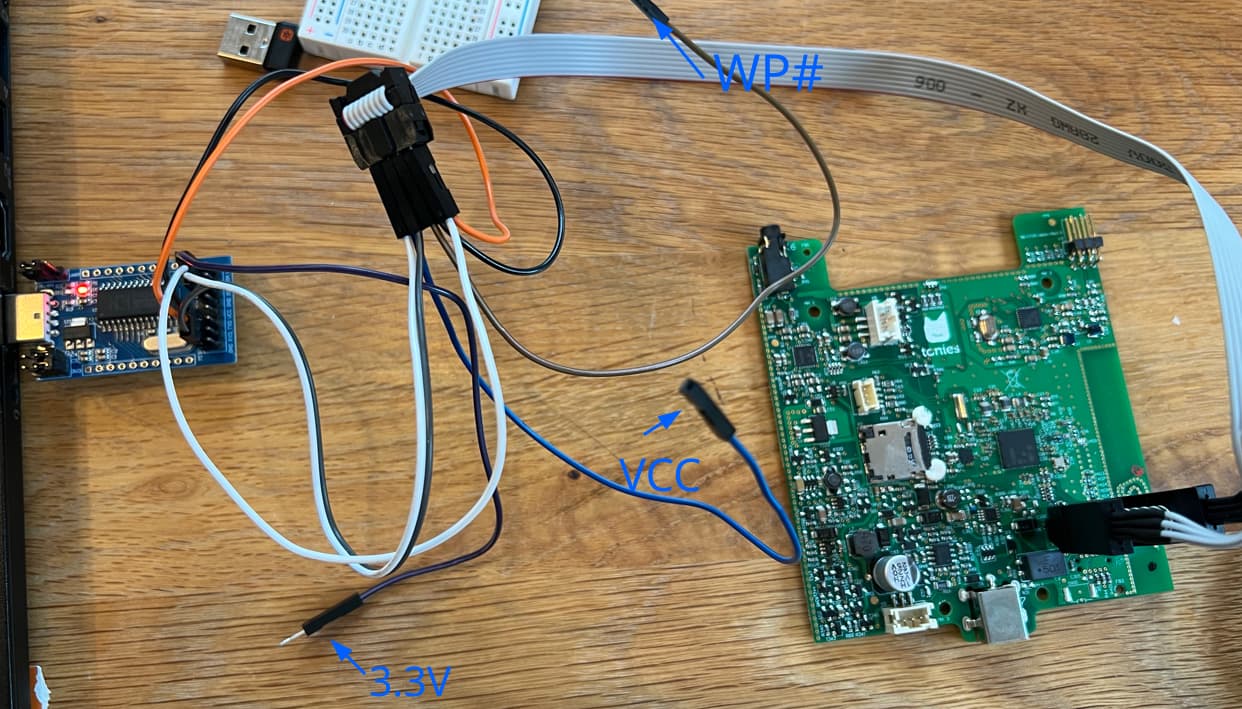
This is the setup which is working for me. I used the small cables to easily connect/disconnect VCC and WP#:
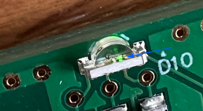
This is how the LED glows in a state which can be reliable used for flashing (in my case):
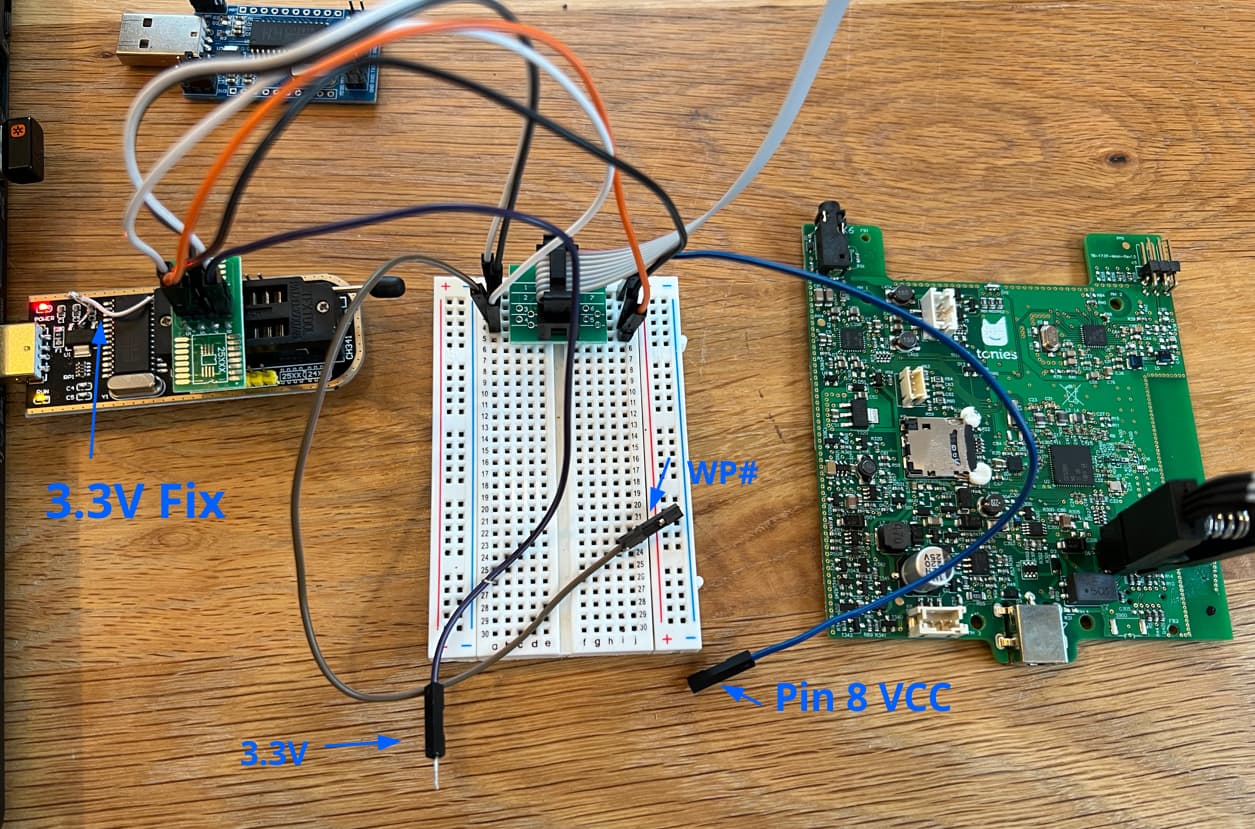
And this setup (with and without breadboard) was consuming too much power and I got never a connection:
I hope it helps someone. Happy flashing!