Hi there,
within this post I try to make an newbie documentation for installing Teddycloud on a ESP32 Box.
![]() ALWAYS READ THE OFFICIAL DOCUMENTATION FIRST
ALWAYS READ THE OFFICIAL DOCUMENTATION FIRST ![]()
![]() DUE HEAVY UPDATES THIS GUIDE MAY BE OUTDATED
DUE HEAVY UPDATES THIS GUIDE MAY BE OUTDATED ![]()
![]() Intro
Intro
We will make use of docker in this write up and try to cover all steps needed, so people with less knowledge may be capable of getting their own private toniescloud.
In this guide we will use a Raspberry Pi OS (every other Linux distribution will be finde too and you should be able to do this on windows too)
![]() Tools
Tools
For this you need a USB UART adapter, almost any adapter that can handle 3.3V should work, I tried two adapters, one wouldn’t work, the one that worked is this one:
https://www.amazon.de/gp/product/B01N9RZK6I/
(Attention USB Mini B :))
The Toniebox has a debug interface, connections for the UART have to be soldered to this, if you can’t really solder like me, the following clamp is a recommendation from the Revoxxcommunity: https://www.amazon.de/gp/product/B0BV79V2DW/
This does not fit exactly, but if you place it on the contacts at a slight angle, it works very well, a photo is attached later in the text.
![]() Hardware
Hardware
The first thing we have to do is unscrew the box, for this we have to unscrew the lid, if you can’t do it like the guys from Revoxx here: https://www.youtube.com/watch?v=GOZRjaEhrcQ
You can use this method: https://www.youtube.com/watch?v=eiMxkXM8YDs
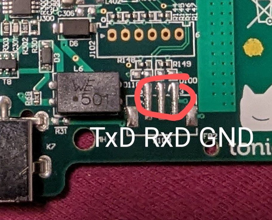
Now that the box is open in front of you, you can see the contacts to which the UART must be connected in the following picture. Here you can either solder a socket, a cable or whatever the hobbyist can think of.
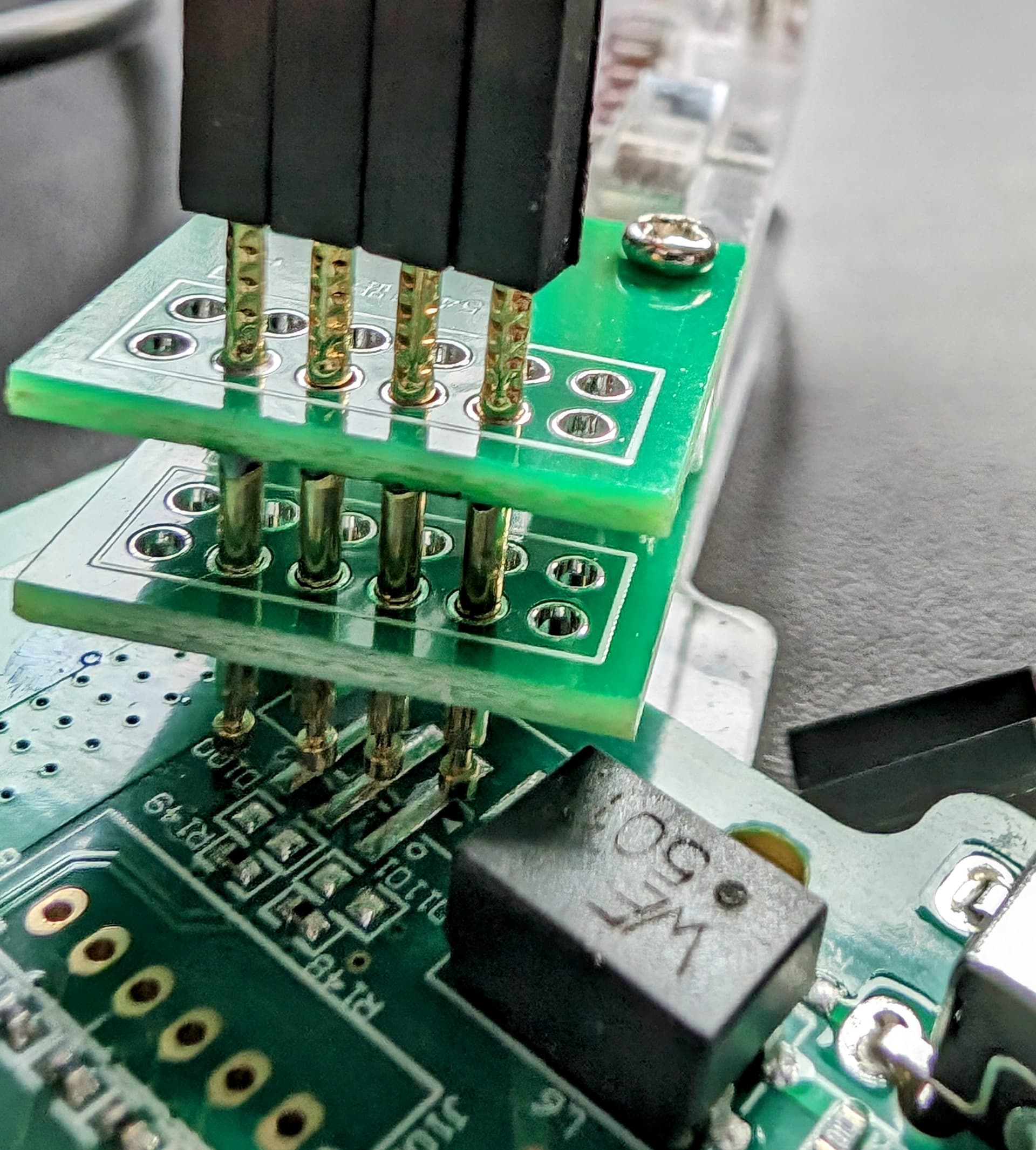
For the non-makers like me, the above-mentioned clamp works wonderfully.
Here you will see the clamp in action, it’s not aligned perfectlys. Try to place the pins as centrally as possible on the contacts:
![]() Software
Software
You may need to connect your Toniebox to your wifi and update its firmware. Many boxes are shipped with a production firmware only that needs to be updated, before the box works as it should.
The installation of the esptool is not absolutely necessary, as the steps for flashing and patching the image can be done in the web interface of the Teddycloud, but I always found it convenient to have the tool at hand in case the browser doesn’t really want to communicate with the UART.
git clone https://github.com/espressif/esptool
cd esptool
sudo python3 setup.py install
Now let’s get and install the teddycloud’s docker containers. The prebuild docker image can be found here: Package teddycloud · GitHub.
If you’re too lazy to write your own docker-compose file, Team RevvoX already got one for you, you can find this in the github repos: teddycloud/docker/docker-compose.yaml at master · toniebox-reverse-engineering/teddycloud · GitHub
If you use the prewritten compose file, please check the routing of port 443.
A ‘docker compose up -d’ will get your teddycloud up:
wget https://raw.githubusercontent.com/toniebox-reverse-engineering/teddycloud/master/docker/docker-compose.yaml
docker compose up -d
If you don’t expect any errors, you should now have teddycloud up and running and you now should start up Chrome and go to your new teddycloud server. You may try any other browser as well, but afaik Chrome gives you the best possible web to serial connection.
When teddycloud is running, let’s test the UART connection, to do this, connect your UART to the USB port of your computer and to the contacts on the Toniebox.
Start a serialmonitor to watch whats happening, I will use ‘screen’ for this, my USB Uart is connected to /dev/ttyUSB0. You can check which device you need, just type ‘dmesg’ into you CLI right after you connected the UART. Here you see the command and the output after starting the Box in normal mode.
screen /dev/ttyUSB0 115200

ESP-ROM:esp32s3-20210327
Build: Mar 27 2021
rst:0x1 (POWERON), boot:0x8 (SPI_FAST_FLASH_BOOT)
SPIWP:0xee
mode:DIO, clock div:1
load:0x3fcd0108,len:0x118
load:0x403b6000,len:0xb84
load:0x403ba000, len:0x2790
entry 0x403b61c0
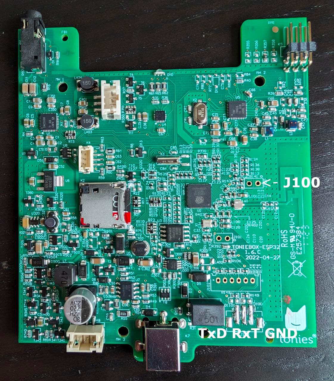
Your output looks similar to this one? Then disconnect the box from the power supply, short the jumper J100. Thanks to Flo we have a unmodded ESP32 board here:
There will be no green light, the LED will only flash one time red, no sounds are played, the output in the serial console looks something like this:
ESP-ROM:esp32s3-20210327
Build: Mar 27 2021
rst: 0x1 (POWERON), boot: 0x0 (DOWNLOAD(USB/UARTO))
waiting for download
Now exit the serialmonitor (ctrl+a, ), switch to the web interface and click on “Read ESP”.
Back to the terminal:
docker exec -it teddycloud bash
cd /teddycloud
teddycloud --esp32-extract data/firmware/ESP32_<mac>.bin --destination certs/client
mv certs/client/CLIENT.DER certs/client/client.der
mv certs/client/PRIVATE.DER certs/client/private.der
mv certs/client/CA.DER certs/client/ca.der
With teddyCloud you can also patch and write the new image with your custom CA and a DNS/IP so the box connects to teddyCloud. If you have a Fritzbox you can set it to tc.fritz.box, if not set it to the IP of teddyCloud.
For Fritzbox: You’ll just have to set the name of your server in your fritzbox to tc (Heimnetz → Netzwerk → Netzwerkverbindungen → bearbeiten).
Now reassemble your box and take a look to ‘docker logs teddycloud --follow’. You should see the box connecting and you now can have starting fun with your teddycloud.
Big thanks to Team revoxx, especially 0xdeadbee who helps out a lot.
Thanks to 3musketiere and Florian, I grabbed your images and infos as well.
To keep it short: Thanks for all the fish from: Telegram: Contact @toniebox_reverse_engineering
![]() Troubleshooting // FAQ:
Troubleshooting // FAQ:
![]() Webinterface can’t connect, no output on serial console
Webinterface can’t connect, no output on serial console
Please recheck the connection with the UART. Be aware, most serial2usb UARTS need to swap TX/RX.
So connect Boards Tx to Rx on your UART. Rx to Tx and GND to GND.
![]() Glibberish output on serial console, reading flash keeps terminating
Glibberish output on serial console, reading flash keeps terminating
Recheck the connection to the debug port on the ESP32. Especially if working with clamps take a look to the connection, is it aligned properly?
![]() After reading flash with webinterface, I cannot reconnect to the serial and flash my patched image
After reading flash with webinterface, I cannot reconnect to the serial and flash my patched image
Reconnect UARTS’s USB connection and reboot the box into debug mode.
Alt: use esptool to flash your patched image. For me the image is found in:
/var/lib/docker/volumes/docker_firmware/_data
The flash command reads:
esptool.py -b 921600 write_flash 0x0 patched[MACADRESS].bin
![]() How can I update my teddcloud instance?
How can I update my teddcloud instance?
Navigate to the location of your docker-compose.yaml
docker compose down
docker compose pull
docker compose up -d
![]() How can I switch to devleopment builds?
How can I switch to devleopment builds?
Edit the docker-compose.yaml:
version: '3'
services:
  teddycloud:
    container_name: teddycloud
    hostname: teddycloud
    image: ghcr.io/toniebox-reverse-engineering/teddycloud:develop
    ports:
    #  - 80:80 #optional
      - 443:443 #Port is needed for the connection for the box
    volumes:
      - certs:/teddycloud/certs
      - config:/teddycloud/config
      - content:/teddycloud/data/content
      - library:/teddycloud/data/library
      - firmware:/teddycloud/data/firmware
    restart: unless-stopped
volumes:
  certs:
  config:
  content:
  library:
  firmware: